
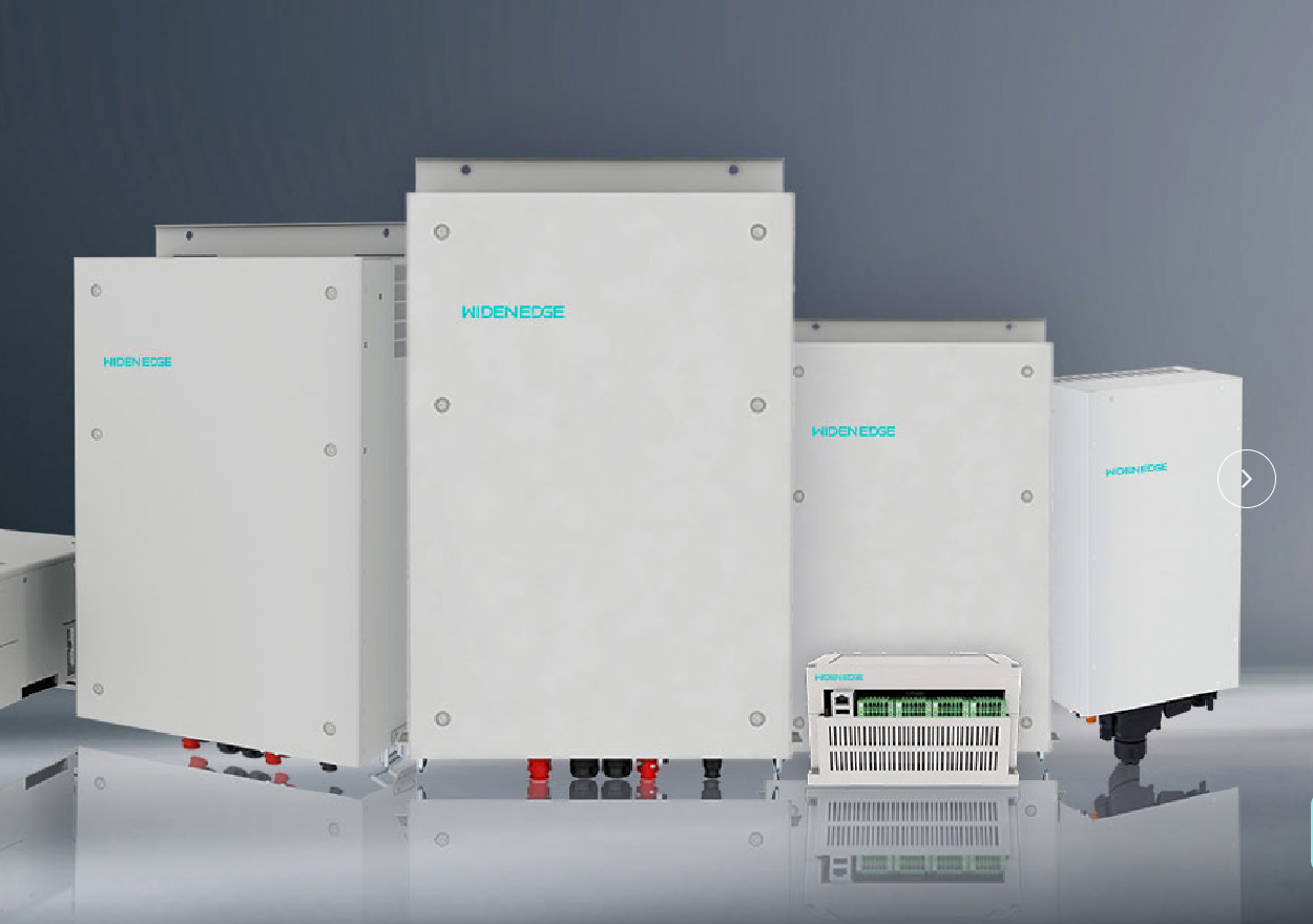
Data-driven introduction and scope
Design decisions for a 60 kW off-grid PV inverter must rest on measured quantities rather than impression. Begin with peak continuous load, daily energy consumption (kWh), and desired autonomy hours; combine those with site solar resource statistics and component efficiencies to form a baseline. For larger storage-scaling scenarios consider equipment such as the 600kW energy storage inverter as a reference point for how power-stage selection influences control architecture and thermal planning. This guide uses empirical thinking: present numbers, compute margins, then iterate on topology and protection.
Site assessment and required datasets
Collect the following datasets before any electrical design. Precise measurement reduces rework.- Peak and sustained load profile (15-minute resolution preferred).- Daily and seasonal energy demand (kWh/day) and required autonomy (hours or days).- Local irradiance database (PVWatts, Meteonorm, or measured pyranometer data).- Temperature extremes and ambient conditions for derating.- Grid availability (if any) and islanding expectations.- Available roof/ground area and PV array azimuth/tilt.These data feed component sizing formulas and risk quantification; do not omit temporal resolution for loads.
Sizing methodology: inverter, PV array, and battery bank
Follow deterministic calculations rather than heuristics. Basic steps:- Inverter sizing: match continuous inverter rating to sustained load with 20–30% margin for startup currents and future load growth. For a nominal 60 kW off-grid inverter, verify surge capability for motor inrush and UPS loads.- PV array sizing: compute daily production requirement = (daily demand / system availability) ÷ (array derate factor). Use common derate factors: module soiling, mismatch, temperature, wiring and MPPT losses (aggregate 0.75–0.90 depending on site).- Battery capacity: required usable capacity (kWh) = daily demand × autonomy factor. Adjust for Depth of Discharge (DoD) and round-trip efficiency: battery nominal capacity = usable capacity ÷ (DoD × round-trip eff). Typical lithium systems assume DoD 0.8–0.9 and round-trip 0.88–0.95; lead-acid requires larger buffers.- Power versus energy distinction: ensure charge/discharge power (kW) matches inverter and peak load concurrently. A 60 kW inverter with a 50 kWh battery may supply power but not provide desired autonomy.Example check: if daily demand = 300 kWh and desired 24-hour autonomy, usable battery needed ≈ 300 kWh; nominal battery ≈ 300 ÷ (0.9 × 0.9) ≈ 370 kWh (approximate method).
Electrical architecture and integration choices
Decide coupling topology and control hierarchy.- DC-coupled system: PV feeds battery/inverter DC bus. Advantages in charging efficiency when large battery present. Requires compatible MPPT and charge controllers.- AC-coupled system: PV inverters inject AC into bus; battery inverter manages AC coupling and charge control. Easier to retrofit and often simpler protection coordination.- Hybrid topologies: combine both depending on generation and storage scale.Protection and control items:- Anti-islanding and synchronization logic must be validated to standards.- Overcurrent protection, selective fusing, and cable-sizing to limit voltage drop and thermal losses.- Grounding and bonding plan consistent with local code and inverter manufacturer instructions.- Thermal management: containerized or enclosed installations must account for ventilation and HVAC load when selecting inverter enclosures.
Commissioning, testing, and field validation
Verification requires staged tests with measurable acceptance criteria.- No-load start, nominal load, and overload tests with recorded waveforms.- Battery charge/discharge efficiency and state-of-charge accuracy checks.- Protection coordination validation: intentional fault simulation at planned clearing times.- Cyber and control verification for inverter communication and supervisory systems.Puerto Rico’s post-2017 microgrid deployments provide concrete lessons: field teams found that commissioning under realistic storm-restoration scenarios exposed gaps in protection settings and spare-part planning that bench tests had not revealed. Learn from these operational incidents and plan endurance tests accordingly.
Common pitfalls and risk mitigation
Frequent errors reduce reliability or increase cost. Avoid:- Undersizing battery energy relative to autonomy goals.- Neglecting thermal effects on inverter rating and derating at high ambient temperatures.- Mixing incompatible communication and BMS protocols without gateway planning.- Insufficient surge margin for motor-starts and transformer inrush.Mitigation tactics:- Add explicit margins in both power and energy budgets.- Specify ambient derating in procurement documents.- Include spare parts and modular replacement strategy for critical power electronics.
Comparison of deployment options
Evaluate trade-offs in straightforward terms.- Centralized stationary system: lower initial component count, more complex site cabling, higher single-point-of-failure risk.- Containerized microgrid approach: factory-integrated protection, thermal control, and simplified site installation; faster commissioning at remote sites and predictable environmental control. For the containerized option consider specific hardware such as a microgrid containerized inverter to reduce on-site engineering time.- Distributed inverters per array string: higher redundancy, easier incremental expansion, but greater system complexity in controls.Select according to priorities: speed of deployment, maintainability, redundancy, and site logistics.
Standards, lifecycle considerations, and procurement notes
Reference applicable standards early: IEEE 1547 for interconnection behavior, IEC 62109 for safety of power converters, and local electrical codes. Specify lifecycle expectations: cycle life for batteries, maintenance intervals for cooling and fans, and firmware update policies for inverters. Procurement documents should demand test certificates, thermal curves, and manufacturer support timelines. Field experience matters more than glossy data sheets: require factory witness testing or third-party witnessed FAT when feasible.
Conclusion: decision logic and ecosystem fit
Make design choice by tracing numbers: loads → energy → PV production → battery energy → inverter power, and then validate with protection and thermal plans. This method reduces surprises and clarifies trade-offs between centralized and containerized solutions. Practical implementations that we have observed converge on modular, tested blocks because they reduce on-site engineering and commissioning time, a fact that speaks to suppliers with integrated systems such as WidenEdge when the project requires predictable performance and streamlined integration.
