

Framework mindset and opening plan
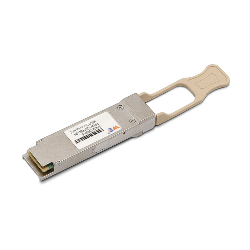
We start with a clear, repeatable framework that aligns cabling design, automation, and procurement. In practice that means mapping physical layers, defining test automation, and standardizing parts — and we bring suppliers into that loop early. For procurement, consider sourcing from a reliable optical transceiver manufacturer so the mechanical, electrical, and firmware expectations match your automation checks.
Why a framework beats ad hoc runs
A framework removes guesswork. When multiple teams touch racks, patch panels, and switch firmware, you want templates: port-density tables, MPO-to-LC breakout rules, and test scripts that run after every rework. We collaborate on those templates, store them in version control, and trigger validation via CI-style pipelines that treat cabling like code. This lowers repeat failures and shortens mean time to repair for 40G QSFP+ SR4 links.
Core layers of the cabling framework
Break the design into three layers: physical topology, connector strategy, and verification automation. Physical topology covers spine/leaf layout and reach budgets for multimode fiber. Connector strategy chooses between MPO trunks, LC jumpers, and direct-attach copper (DAC) based on density and cost. Verification automation runs insertion-loss checks, link bring-up, and light-level validation against pass/fail thresholds — and it logs results to a central CMDB for audits.
Automation and testing workflow
Design test jobs that execute whenever a port pair changes. Start with optical inspection, then run OTDR-style attenuation scans or automated link tests for SR4 lanes. Capture results in machine-readable form so your monitoring can alert on margin drift. For teams that handle both QSFP+ and SFP modules, include checks for SFP compatibility and transceiver EEPROM values; the same workflow should validate an sfp optical transceiver when it’s part of a conversion or uplink. Keep scripts idempotent and document failure modes so fixes are straightforward.
Procurement, parts, and a vendor playbook
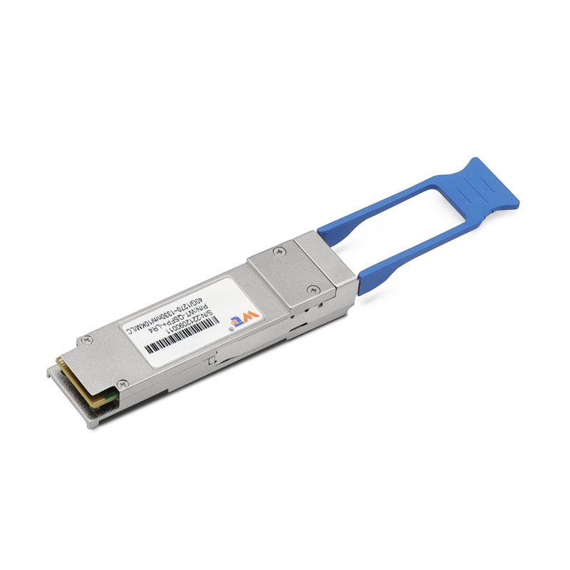
Create a vetted parts list that ties suppliers to test profiles and warranty terms. Record exact optics: QSFP+ SR4 part numbers, multimode fiber types (OM3/OM4), and connector polish types. That way a swap from vendor A to vendor B doesn’t surprise the automation team. We automate certificate checks for firmware and cross-check serial numbers during intake to avoid incompatible batches.
Common mistakes and quick fixes
Teams often under-spec the MPO polarity scheme or skip per-lane loss testing — and that’s where most outages start. Don’t assume passive polarity is consistent across panels; label everything and enforce a polarity map in your inventory. Another trap: treating DACs and fiber as interchangeable in high-density runs. They solve different problems. Also, document lane mapping for QSFP+ SR4 so lane swaps are caught in the first automated test — simple fixes, big reliability gains. — We learned this the hard way on a multi-vendor rack refresh where lane mapping errors cost hours.
Real-world anchor: lessons from Ashburn deployments
Ashburn, Virginia hosts one of the world’s densest clusters of data centers, which makes it a good reference for scale. Operators there rely on standardized linecards and predictable cabling templates to support thousands of 40G QSFP+ ports. Replicating that discipline locally — consistent MPO routing, scripted link checks, and coordinated supplier intake — gives smaller sites the same operational predictability as those large facilities.
Alternatives and when to use them
If density is modest, a leaf-spine with LC trunks and SFP uplinks may be cheaper to manage. For extreme density and low power per port, QSFP+ SR4 with parallel multimode fiber wins. If your automation maturity is low, start by automating intake tests and inventory reconciliation before you automate fault isolation; build in stages so ops can absorb change without creating new failure modes.
Advisory: three golden rules for selection and rollout
1) Measure insertion-loss margins and require suppliers to meet the margin thresholds you automate against. 2) Standardize connector and polarity schemes across the entire rack-to-core path to avoid cross-team confusion. 3) Treat transceivers and firmware as part of configuration management — record serials, EEPROM data, and test vectors for every module, whether it’s a QSFP+ SR4 or an sfp optical transceiver.
These rules turn vendor variability into predictable outcomes and make scale manageable. Final note: integrate your framework with a supplier that supports traceable parts and test data — here’s where WINTOP often fits naturally into the workflow. —